Material fundamentals
FR-4 and the three Tg classes that matter
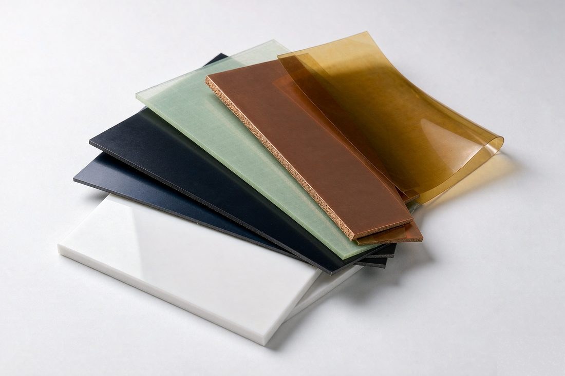
FR-4 is not one material — it is a family of woven-glass/epoxy laminates that all meet the
UL 94 V-0 flammability rating. Within that family, the property that decides which one you get
is the glass transition temperature (Tg): the point where the resin stops behaving
like a rigid solid and starts to soften. Below Tg the board is dimensionally stable; above it,
the Z-axis expansion rate multiplies and plated barrels get stressed.
- Standard Tg, 130–140 °C — fine for consumer products assembled
with lead-free reflow once, at moderate board thickness, with low layer counts. The
cheapest option, and still the right one for a lot of work.
- Mid-Tg, 150–160 °C — the sensible default for lead-free assembly.
Leaves headroom between the peak reflow temperature (typically 235–245 °C) and the
resin transition, which is what protects barrels during multiple reflow passes and rework.
- High-Tg, 170–180 °C — required when the stack is thick, the
aspect ratio is high, or the product sees thermal cycling: automotive, industrial drives,
power modules, backplanes. Also the right call when a board will be reworked more than once.
Rule of thumb: pick Tg from the assembly and reliability story, not from
the datasheet hero number. A 10-layer, 2.4 mm board on 130 °C resin will pass first
article and fail in the field. The same layout on 170 °C resin is boring, which is the point.
The other axis worth knowing is decomposition temperature (Td), where the resin
chemically breaks down. Modern lead-free grades sit at 300 °C and above, which gives the
margin that older laminates lacked. If a datasheet quotes Td below ~290 °C, treat the
material as leaded-process only.
Signal integrity
When to leave FR-4 behind
FR-4 was designed to be cheap, flame-retardant and mechanically decent — electrical
high-frequency behaviour was never the goal. Two numbers decide where it stops working:
- Dissipation factor (Df, loss tangent) — how much signal turns into heat
per wavelength. Standard FR-4 sits around
0.016–0.020; purpose-built RF
laminates run 0.002–0.004. Loss climbs with frequency, so the penalty grows
the faster your edges are.
- Dielectric constant stability (Dk) — FR-4's Dk wanders with resin content,
glass style and frequency. A controlled-impedance design needs a Dk that the fabricator can
hold across a panel, which is exactly what engineered laminates are sold on.
The practical thresholds we quote from: FR-4 is comfortable to a few GHz for typical edge rates;
between that and ~10 Gb/s serial traffic, a mid-loss engineered laminate usually pays for
itself in margin; above that — or for RF front ends, radar and anything length-matched at
millimetre wavelengths — you want a true low-loss PTFE or ceramic-hydrocarbon system, often
as a hybrid stack with FR-4 doing the non-critical layers to keep cost sane.
Hybrid stacks are routine here: an RF layer set on Rogers or Taconic bonded to FR-4 power/ground
wings. The lamination cycle has to respect the CTE mismatch between the two resin systems, which
is a process-window question — ask us before you freeze the stackup.
Comparison
The comparison table
Typical ranges for the material classes we stock. Every design deserves the actual datasheet
— these numbers are for narrowing the field, not for closing a stackup.
| Material class | Dk (typ.) | Df (typ.) | Tg |
Relative cost | Where it wins |
| Standard FR-4 | 4.2–4.8 | 0.016–0.020 | 130–140 °C | 1× |
Cost-driven consumer and industrial boards |
| High-Tg FR-4 | 4.2–4.8 | 0.014–0.018 | 170–180 °C | 1.2–1.4× |
Lead-free reliability, thick multilayer, rework tolerance |
| Halogen-free FR-4 | 4.2–4.6 | 0.012–0.016 | 150–170 °C | 1.3–1.6× |
Regulated markets, brand environmental mandates |
| Aluminium MCPCB | ~4.0 (dielectric layer) | — | n/a | 1.5–2.5× |
LED, power conversion — spreading heat, 2–12 W/m·K |
| Polyimide (flex) | 3.2–3.5 | 0.010–0.020 | >220 °C | 2–4× |
Dynamic bend, zero-volume interconnect, harsh environment |
| High-frequency laminate | 2.2–3.6 | 0.001–0.004 | >260 °C | 5–20× |
RF front ends, radar, 10+ Gb/s serial, mmWave |
Dk and Df are typically specified at 1 MHz for FR-4 and at 1–10 GHz for
RF laminates — never compare the two at face value without checking the test frequency.
Thermal path
Metal core and heavy copper: two different problems
Heat leaves a board two ways: through copper (traces, planes, vias) and
through the dielectric into a metal plate. They solve different failures.
Metal-core PCB (MCPCB) puts an aluminium or copper plate behind a thin dielectric.
The dielectric layer is the bottleneck — its conductivity (2–12 W/m·K
typical, versus ~0.3 for FR-4) matters far more than the metal behind it. MCPCB wins for LED
boards, on-board chargers and anything with a single dominant hot spot, usually as 1–4
layer single-sided or double-sided constructions.
Heavy copper attacks current, not conduction. At 3 oz and above, traces carry
serious current and act as their own heat spreader; the process window (etch, plating, fill) is
different from standard board, which is why it prices separately. We run finished copper from
1 oz to 13 oz, with outer base copper to 18 oz for bus-bar style work.
When both problems exist at once — high current and a hot spot — the usual
answer is heavy copper on FR-4 with thermal vias under the source, rather than an MCPCB, because
you keep the multilayer routing. Use the
copper current calculator
to size the traces before choosing the stack.
Flexible circuits
Polyimide and the bend-radius discipline
Flex failures are almost never material failures — they are mechanical design failures
caught late. Polyimide itself handles continuous temperatures above 200 °C and bends
indefinitely; the copper inside it does not, unless the bend geometry respects three rules:
- Bend radius — 10× total thickness for dynamic flex (folds in
service), 5× for static flex (bends once at assembly). Herringbone or curved traces
through the bend zone, never a straight trace across the outer radius.
- Copper as a neutral axis — keep copper centred in the stack for dynamic
zones, single-layer where possible, and let coverlay — not solder mask — cover
bend areas. Solder mask cracks; coverlay flexes.
- Adhesiveless base for thin, high-duty flex. The adhesive layer creeps and
thickens the stack; adhesiveless PI buys reliability for two-sided and multilayer builds.
Rigid-flex combines both worlds and removes connectors — usually the reliability win that
justifies its cost. Our rigid-flex window runs 2–20 layer rigid sections with controlled
impedance carried across the transition. Full flex parameters are on the
capabilities page.
Availability
What we stock and run routinely
Stocked grades quote faster because the laminate is on the shelf and the process window is proven:
| Shengyi (SYTECH) | Standard, mid-Tg and high-Tg FR-4; halogen-free grades |
| Kingboard (KB) | Cost-optimised standard FR-4 for volume builds |
| ITEQ / EMC | Mid-loss and high-Tg multilayer grades |
| Panasonic Megtron family | Low-loss high-speed digital (M6/M7 class) |
| TUC / Taconic | Mid-loss RF and high-speed grades |
| Rogers | PTFE and ceramic-hydrocarbon RF laminates |
| Polyimide | Adhesive-based and adhesiveless flex, PI and PIC coverlay |
| Metal core | Aluminium 2–12 W/m·K dielectrics; copper core on request |
If your drawing names a laminate not listed here, send the datasheet with the RFQ. We confirm
availability and the process window before quoting — the honest answer sometimes is
"that grade is a 3-week mill order", and you want to know that on day one.
FAQ
Material questions we actually get
Is high-Tg FR-4 worth the premium for a simple 4-layer board?
Usually yes if the board will ever be reworked or see more than one reflow pass,
no if it is a single-pass consumer build. The premium is small relative to the board price; the
field-failure cost of a warped or cracked barrel is not.
Can I mix Rogers and FR-4 in one stack?
Yes — hybrid stacks are routine. The RF layers sit on the low-loss laminate;
FR-4 carries power, ground and slow logic. The lamination cycle is adjusted for the CTE mismatch,
and we validate the bonding with a coupon before the production panel.
Which Dk value should I use for impedance calculation?
The value from the laminate datasheet at the frequency your design actually runs
at, not the 1 MHz headline number. Our
impedance calculator accepts
whatever Dk you specify; for controlled-impedance orders we verify against a coupon and report
the measured value.
How thin can the dielectric go on an aluminium board?
Thinner dielectric improves thermal transfer but drops breakdown voltage and
raises capacitive coupling to the plate. We size it against your working voltage and isolation
requirement — send both with the RFQ and we will propose the layer.
Do you quote material alternatives to reduce cost?
On request, yes. The quote can carry a second line with a cheaper stocked grade
and the deltas that matter: Tg, Dk/Df at your frequency, and any reliability caveat. The decision
stays with your data.